Residential
Yzerfontein sits on the West Coast of South Africa, in a landscape classified as Strandveld — a coastal subtype of the Cape Floristic Region, one of the world's six floral kingdoms and a UNESCO World Heritage biome. The Strandveld is not a backdrop. It is dense, salt-tolerant, wind-sculpted scrub that grows right to the building line: Metalasia, Passerina, Chrysanthemoides — low, tough, and tenacious, shaped by the prevailing southerly into forms that hug the ground.
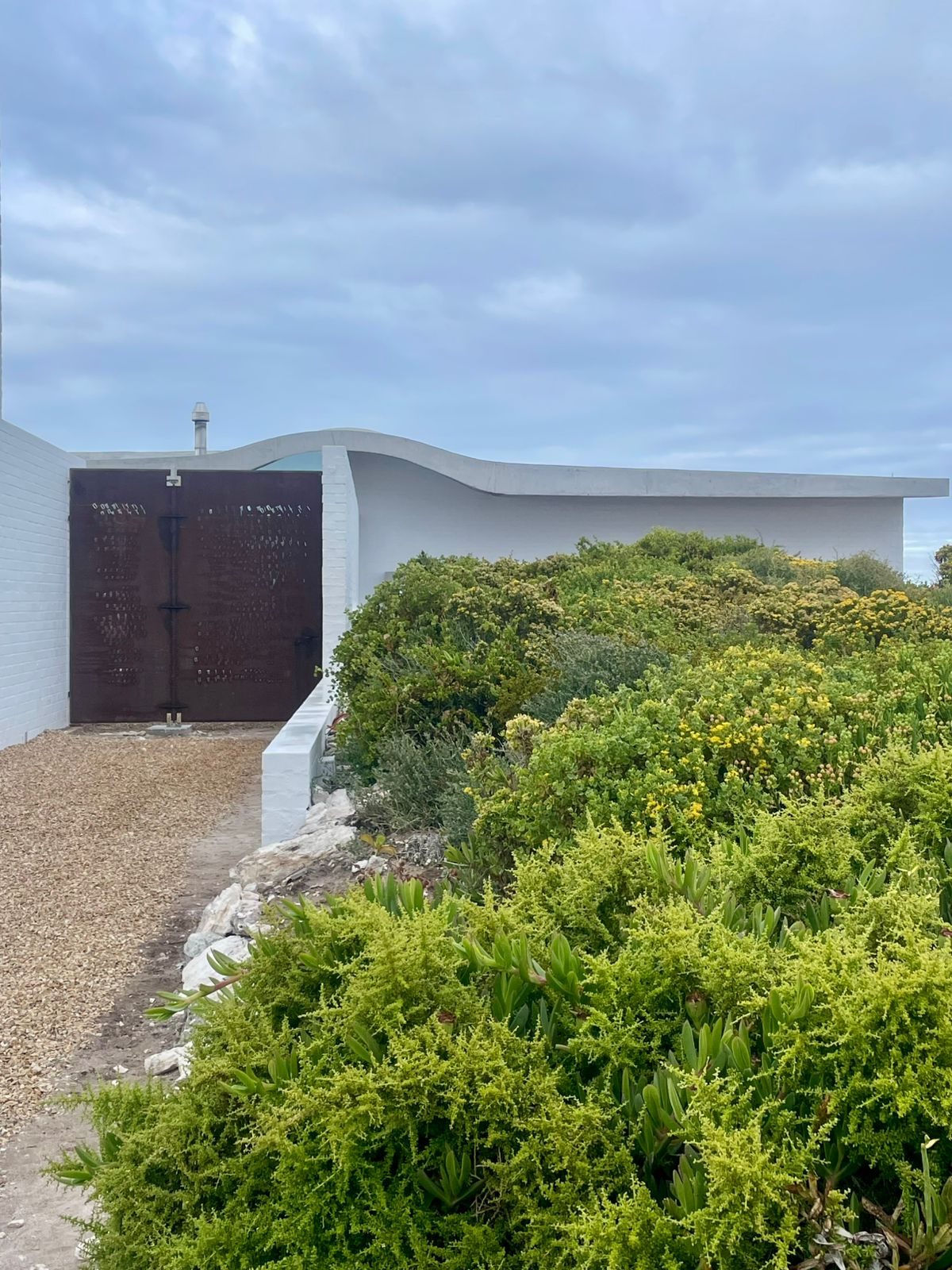
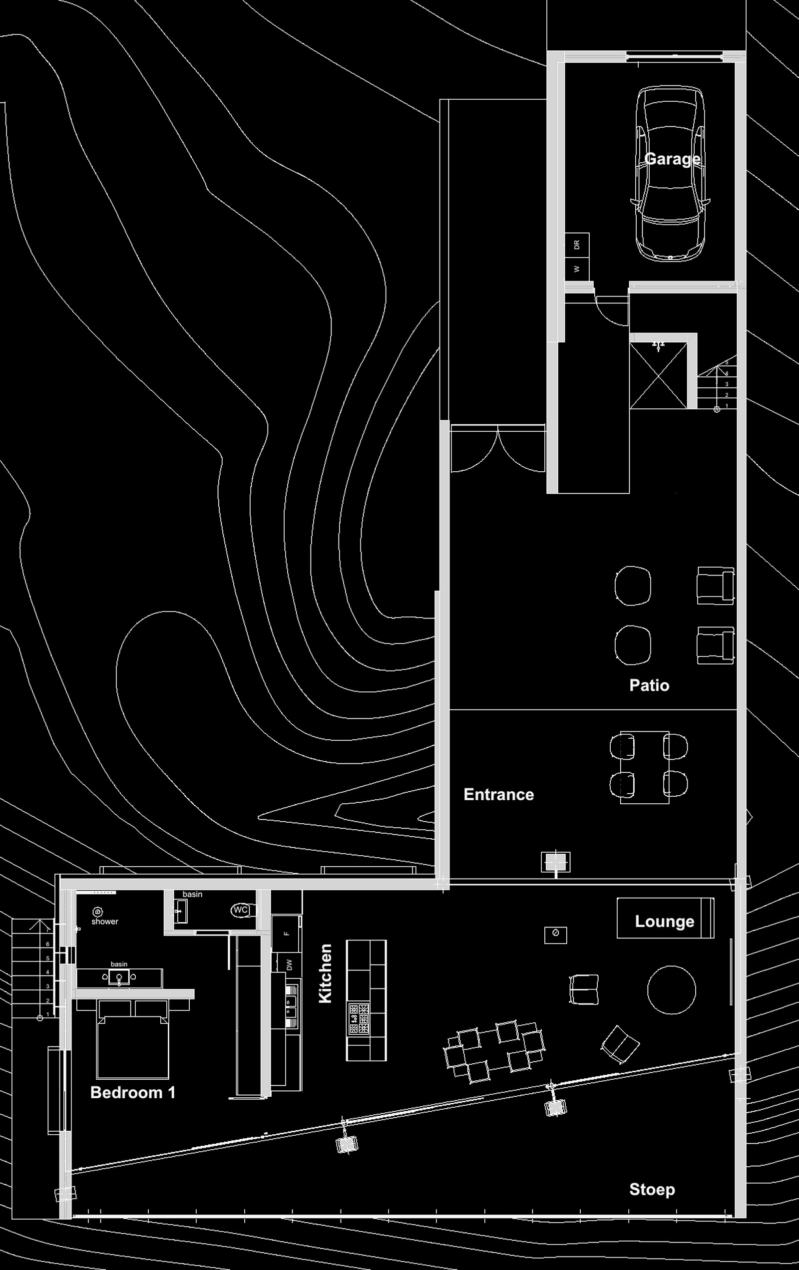
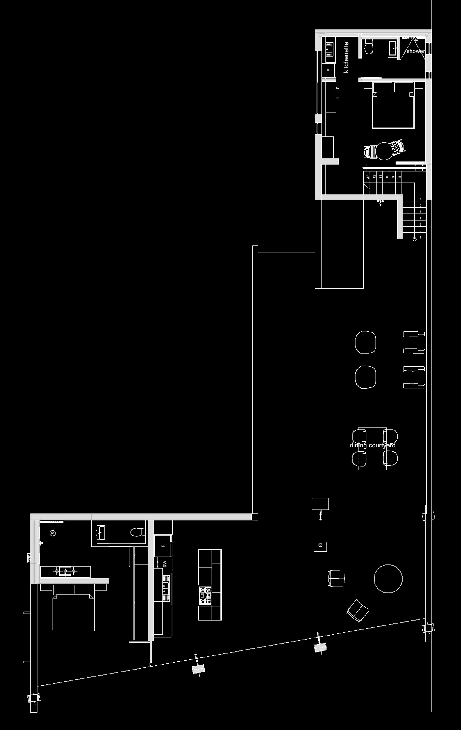
The building is dug approximately 1.2 metres into the site so that it sits below the Strandveld canopy and disappears behind it. From the road, almost nothing is visible. The shell roof — the primary architectural move — reads as a single rounded form rising just above the fynbos line, shaped like the dunes and wind-worn geometry the landscape itself produces. The stoep faces south, looking out over the scrub toward the Atlantic.
.jpg)
.jpg)
.jpg)
.jpg)
.jpg)
.jpg)
.jpg)
The perimeter beam is built up from two mild steel U-channels placed back to back, with a continuous hardwood gasket sandwiched between them. The gasket is a thermal break — it interrupts the steel-to-steel contact that would otherwise conduct heat directly between the inside and outside of the building, turning the beam into a cold bridge. The two channels are bolted through the wood, the assembly behaving as a single composite section.
The beam does not sit on the concrete columns — it hangs from them. A triangulated stainless steel rod connects beam to column head, putting the rod in tension and keeping the beam face flush with the column face. The effect is a floating datum line: the glass sliding system below it appears to have no visible support, reading instead as a continuous plane of glass that rises from the floor and terminates against the underside of the beam.
Above the beam, frameless glass panels connect directly to the curved soffit of the concrete slab, sealing the gap between the sliding system and the shell without a frame or transom. The result is an uninterrupted glass surface from floor to ceiling — the ocean and sky visible as a single unbroken field from inside the living space.
.jpg)
.jpg)
.jpg)
.jpg)
.jpg)
.jpg)
The roof is a concrete shell: two flat planes at different gradients, connected by a freeform shell surface that floats above the living spaces on a series of tapered columns. The geometry was developed entirely in Rhino and Grasshopper. Early design iterations explored a honeycomb plywood shell — STP files generated for 5-axis CNC cutting — before the decision was made to cast the form in concrete. The computational logic carried forward: the shell's curvature is structurally optimised, not formally arbitrary. The form follows the loads.
The shell roof carries a lineage. Felix Candela (1910–1997) — Spanish-born engineer and architect, working in Mexico from 1939 — spent his career demonstrating what thin concrete could do when shaped correctly. His hyperbolic paraboloids and warped shells at Los Manantiales (1958), the Bacardí rum factory (1960), and the Chapel of Lomas de Cuernavaca (1958) achieved enormous spans with shells just 4cm thick. He built by geometry: the ruled surface eliminated the need for complex formwork because straight timber planks could be laid along the straight-line generators of the curve. Structure and economy emerged from mathematical precision rather than material bulk.
Candela's influence here is not formal imitation but methodological kinship. The shell at Yzerfontein is a different beast — a freeform double-curvature surface generated parametrically rather than drawn analytically — but the underlying conviction is the same: that the most direct path between geometry and load is also the most beautiful.
Grasshopper is a visual programming environment that runs inside Rhino. Instead of drawing geometry directly, the designer writes a script — a network of connected nodes, each performing one operation — and the geometry is the output of that computation. Change one parameter and the entire surface updates. The shell here was not modelled; it was calculated.
The drawings below show two outputs of the same script. One is the three-dimensional shell surface; the other slices that shell into wafer panels, unrolls each one flat, and numbers them across the sheet — 1,440 components across 60 rows and 24 columns, no two the same shape because no two sit at the same angle. The numbering is automatic, assigned before a single cut is made.
The result is a kit of parts. The structural unit is not a single panel but a cell — five pieces forming an open box, one flat lid over four walls, glued edge to edge, like a rectangular beehive cell. Each cell sits at a slightly different angle to its neighbour, and the accumulated difference across 288 cells produces the curve. The craftsman receives a flat pile of identically green, uniquely shaped plywood pieces and a schedule; each part has one correct position and orientation, so the work is pure assembly. All the complexity lives in the script.
.jpg)
.jpg)
.jpg)
-dark.jpg)
-dark.jpg)
The entrance door is 5mm mild steel, laser-cut with a perforation pattern generated in Grasshopper. The pattern is not abstract geometry — it is the Greek word σπίτι (spiti: home). The word is used as a single module: Grasshopper takes the whole word and distributes it across the steel surface at varying scales and rotations, controlling overlap within defined thresholds. The result is a field of the word "home" — dense in places, sparse in others — that filters afternoon light into the entry sequence.
The door is frameless, weighs 220kg, and requires five people to move. It rests on a plate at the floor carrying a single ball bearing and pivots on that; at the top a wishbone-triangulated bracket is wedged to the wall in steel — a technique reminiscent of the restoration methods Jaco encountered when visiting the Colosseum during his Rome scholarship, where massive steel belts and wedges were used to pull the inner and outer skin of the leaning walls together, locking structure through tension and compression rather than mortar alone.
The pivot door clears the walls without a frame. The lock is a sliding bolt — a medieval mechanism reduced to its principle and machined in-house — secured with a 25/10/25 euro cylinder.
The door and the shell share the same computational method: a Grasshopper algorithm that generates complex surface behaviour from a simple rule. One does it in concrete over a span. The other does it in steel across a flat plate.
The pivot gate was installed by hand — an endeavour that fell outside the normal boundaries of architectural work. Architect Jaco Booyens was joined by colleague architect Shawn Scriven and Hanneke Benade-Booyens, whose physical help and patience made the installation possible.
.jpg)
.jpg)
.jpg)
.jpg)
.jpg)
.jpg)
.jpg)
.jpg)
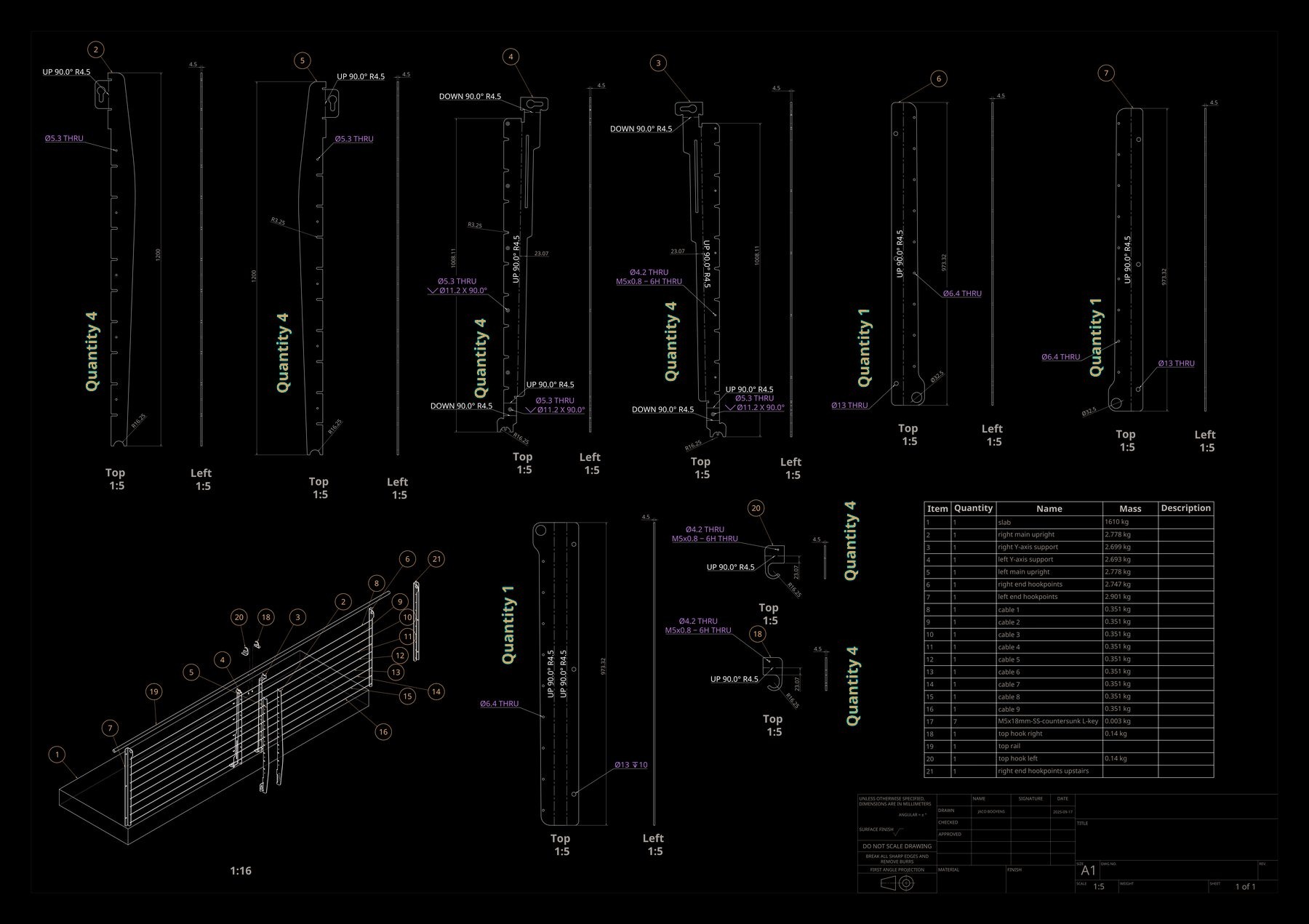
The balustrade is a fully digital design-and-supply project. Modelled entirely in Onshape, the components were laser-cut and CNC-folded directly from digital files — no traditional fabrication drawings, no intermediate translation. The design moved from screen to manufacture without leaving the digital environment.
The balustrade was installed on site by architect Jaco Booyens and Hanneke Benade-Booyens. Like the entrance door, it represents a category of work that sits between architecture and making — where the architect designs, supplies, and installs, closing the gap between drawing and building completely.
.jpg)
.jpg)
.jpg)